No products
BLOG NEWS
Search on blog
Follow us on facebook
Top sellers
-

Proto Shield Plus STARTER KIT
This kit is the ideal solution for those who want to start to prototype...
69,90 € -

Proto Shield Plus LCD KIT
Prototype with ARDUINO / GENUINO boards without having a lot of wires...
56,00 € -

SMD to breadboard adapter (10 pcs pack)
Easily adapt SMD devices to 2.54mm prototyping breadboards.
3,90 € -

Proto Shield Plus BASE KIT
Prototype with ARDUINO / GENUINO boards without having a lot of wires...
52,00 €
Getting the MKR2UNO Plus out of the box
Published : 02/24/2019 17:18:51
Categories : Proto Shield Plus
Getting the MKR2UNO Plus board out of the box
The MKR2UNO Plus comes in your hands as shown in the picture below.
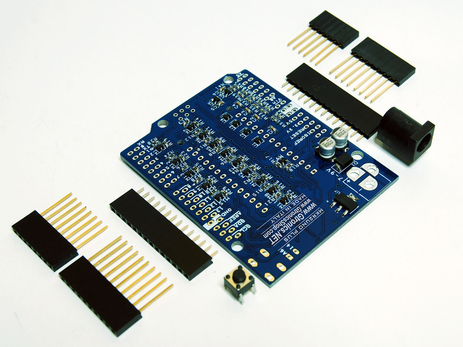
The MKR2UNO Plus consists of:
- 1x MKR2UNO Plus PCB with all SMD components
- 2x 14 way, 2.54mm pitch, headers
- 2x 8 way, stackable, 2.54mm pitch, headers
- 1x 6 way, stackable, 2.54mm pitch, header
- 1x 10 way, stackable, 2.54mm pitch, header
- 1x pushbutton
- 1x 2.5mm DC connector
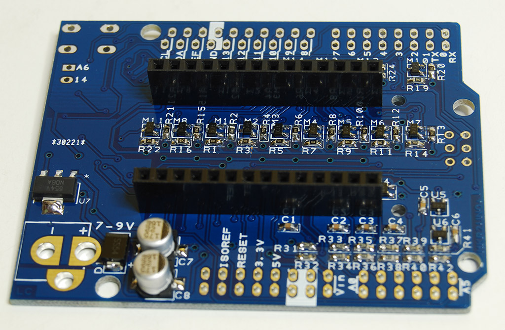
Assembling the 14 way headers
First you have to solder the two 14 way headers as shown in the picture below.
Assembling the reset pushbutton and the 2.5mm DC connector
Even if it is not mandatory, since the board works properly without these two items, you may choose to solder the reset pushbutton and the 2.5mm DC connector.
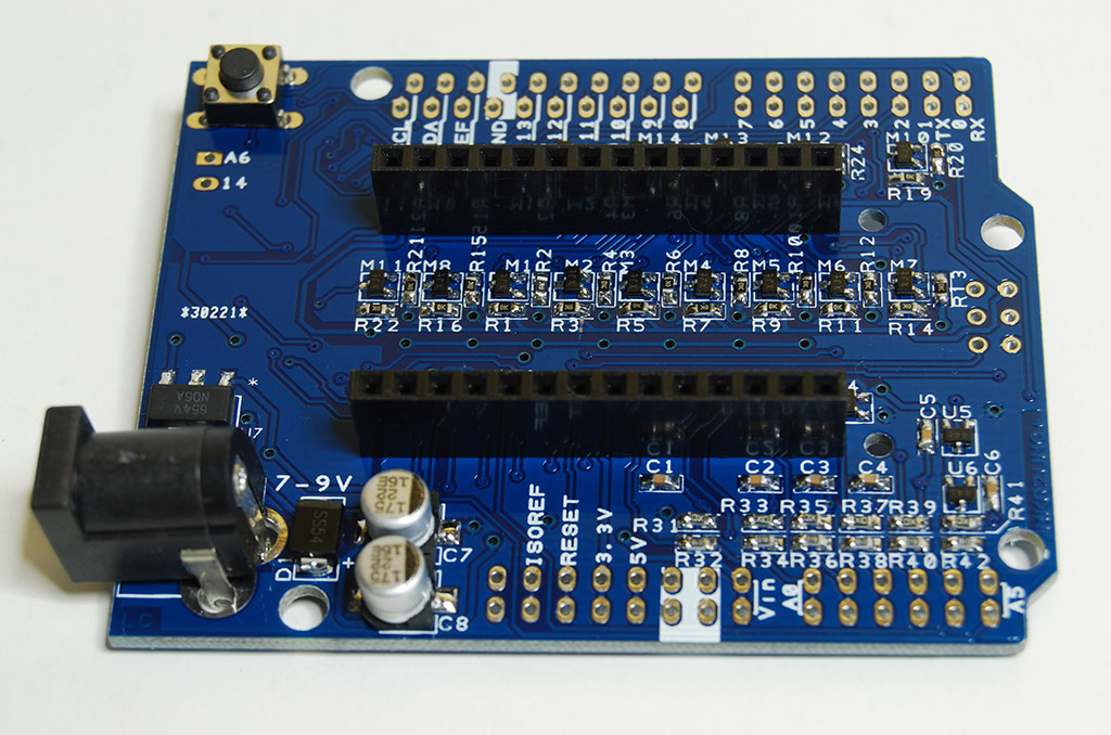
Assembling the reset pushbutton and the 2.5mm DC connector
Assembling the stackable headers
Stackable headers can be soldered in two differt way: the “standard” way or the “long headers” way.
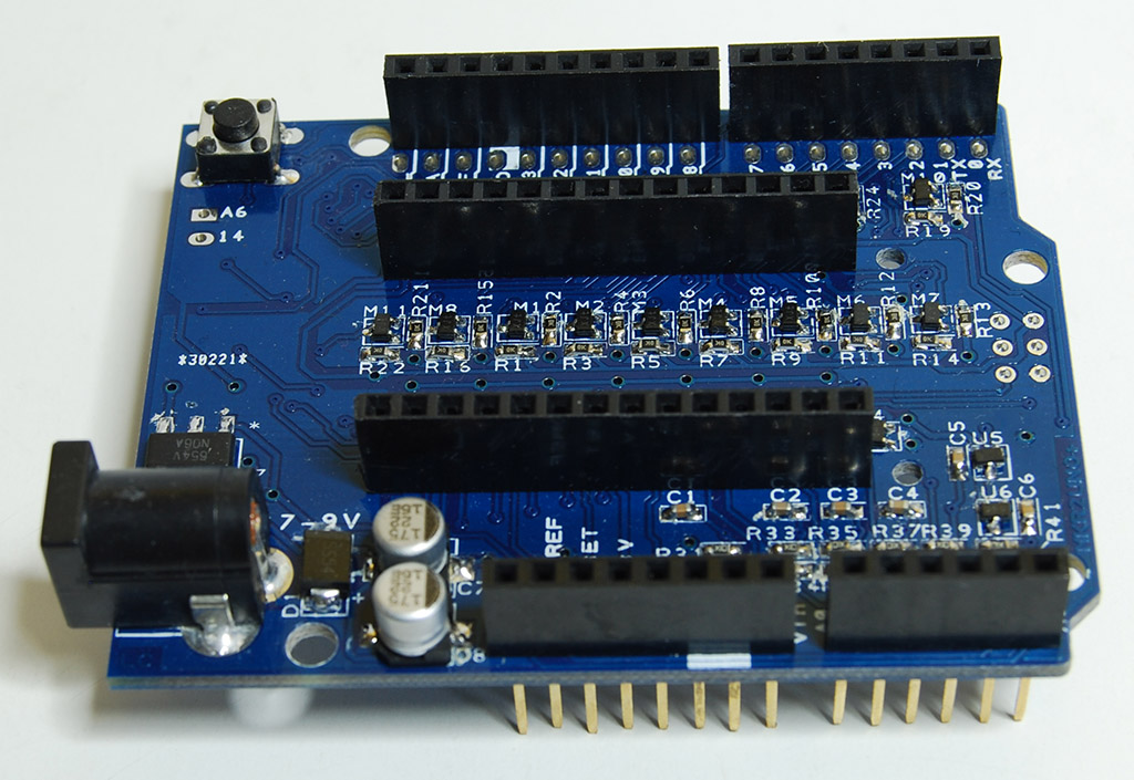
Assembling the stackable headers in the “standard” way
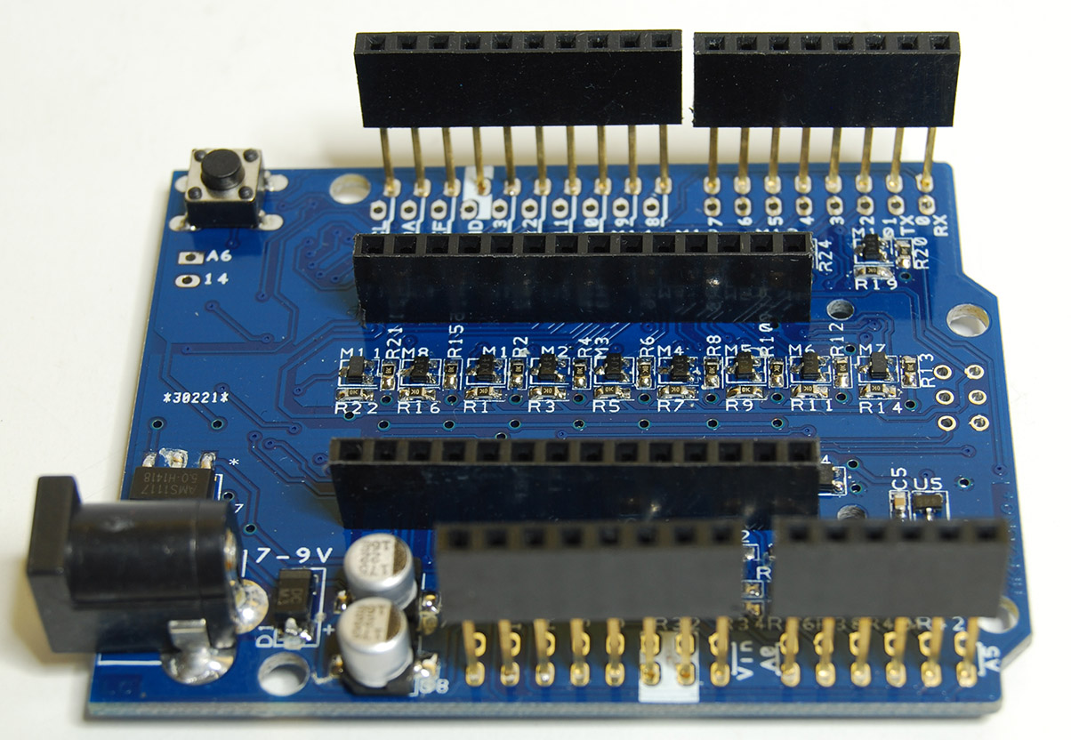
Assembling the stackable headers in the “long headers” way
To better understand why you should choose one way or the other, you have to consider the Arduino MKR board and the environment you are going to use in your project.
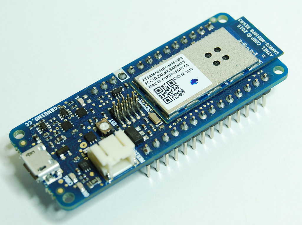
Arduino MKR1000 with pin stripes
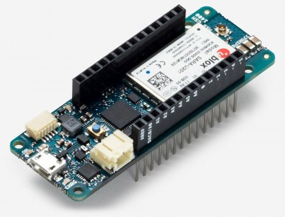
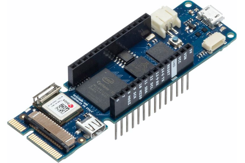
Arduino MKR GSM 1400 and MKR Vidor 4000, both with stackable headers
The “standard” way allows the MKR2UNO Plus to fit both stackable headers and pin stripes boards.
The “long headers” way allows the MKR2UNO Plus to fit only pin stripes boards.
Unless you are going to use an Arduino MKR board with pin stripes AND your project needs a “long headers” layout, we suggest you to solder them in the “standard way” which allows the MKR2UNO Plus to fit any Arduino MKR board.
Related products
Introducing the new MKR2UNO Plus board
Read more
Published : 12/16/2018 16:30:08

 USING A 16x2 LCD DISPLAY WITH THE IoT PROTO SHIELD PLUS
  What does Paolo Aliverti say about the IoT Proto Shield Plus?
  USING AN SSD1306 128x32 OLED DISPLAY (I2C type) WITH THE IoT PROTO SHIELD PLUS
  USING AN SSD1306 128x64 OLED DISPLAY (I2C type) WITH THE IoT PROTO SHIELD PLUS
  I2C Bus on the IoT Proto Shield Plus